Home> Company News> Hydraulic Pump Schematic Diagrams: Understanding the Basics
- AddressNorth Tan Street, Jinan,Shandong
- Factory Address123 Ubi Ave 3 #12-30 Frontier Singapore 408867
- Worktime9:00-18:00(Beijing time)
- Phone(Working Time)86 0531-8299 9952
Hydraulic pump schematic diagrams are critical tools in understanding and troubleshooting hydraulic systems. These diagrams provide a visual representation of the system's components, their interconnections, and how they work together to perform specific tasks. They help operators and maintenance personnel quickly identify problems and take corrective actions, ensuring that the hydraulic system operates efficiently and effectively.In this article, we'll explore the basics of hydraulic pump schematic diagrams, including their components, types, and importance in maintenance and troubleshooting. We'll also provide tips on reading and interpreting hydraulic pump schematic diagrams, and discuss best practices for creating and using them effectively.

Understanding the Components of a Hydraulic Pump Schematic Diagram
A hydraulic pump schematic diagram is a graphical representation of a hydraulic system that uses symbols and notations to illustrate the various components and flow paths of the system. The schematic diagram typically includes the hydraulic pump, valves, cylinders, motors, filters, and other components that are part of the hydraulic system.
One of the key components of a hydraulic pump schematic diagram is the hydraulic pump itself. The hydraulic pump is responsible for generating the fluid flow that powers the system. There are several types of hydraulic pumps, including gear pumps, vane pumps, and piston pumps, each with their own unique features and advantages.
Another important component of a hydraulic pump schematic diagram is the valves. Valves are used to control the flow and pressure of the hydraulic fluid as it moves through the system. There are many different types of valves, including pressure relief valves, check valves, flow control valves, and directional control valves, each with their own specific functions.
Cylinders are also an essential part of a hydraulic pump schematic diagram. Cylinders are responsible for converting the hydraulic pressure into linear motion, which can be used to power machinery or other mechanical systems. There are several types of cylinders, including single-acting cylinders, double-acting cylinders, and telescoping cylinders, each with their own unique features and benefits.
Motors are another key component of a hydraulic pump schematic diagram. Hydraulic motors convert the hydraulic energy into rotary motion, which can be used to power machinery or other mechanical systems. Like cylinders, there are several types of hydraulic motors, including gear motors, vane motors, and piston motors, each with their own specific advantages.
Filters are also an important part of a hydraulic pump schematic diagram. Filters are used to remove contaminants and impurities from the hydraulic fluid, which can help to prolong the lifespan of the hydraulic system and prevent damage to the components. There are many different types of filters, including strainers, screen filters, and high-pressure filters, each with their own specific filtration capabilities.
Different types of hydraulic pump schematic diagrams
There are several different types of hydraulic pump schematic diagrams, each with its own unique characteristics and applications. The most common types include:
-
Line diagrams: This is the most basic type of hydraulic pump schematic diagram. It consists of a simple drawing of the hydraulic system's component parts and the pipes or tubes that connect them. Line diagrams are used primarily to provide an overview of the system's layout and are not suitable for detailed troubleshooting.
-
Cutaway diagrams: This type of hydraulic pump schematic diagram shows the internal components of the hydraulic pump and other system components. Cutaway diagrams are useful for understanding how the pump works and for troubleshooting problems with the pump itself.
-
Block diagrams: Block diagrams are similar to line diagrams, but they use blocks or rectangles to represent the different components of the hydraulic system. The blocks are connected by lines that represent the hydraulic fluid flow. Block diagrams are useful for providing a detailed overview of the system's layout and for troubleshooting problems with the system as a whole.
-
Schematic diagrams: Schematic diagrams are the most detailed type of hydraulic pump diagram. They use symbols and notations to represent each component of the system, including pumps, valves, actuators, and sensors. Schematic diagrams are used primarily for troubleshooting and repair.
-
Pictorial diagrams: Pictorial diagrams are similar to schematic diagrams but use realistic images of the system components rather than symbols. They are useful for providing a clear, intuitive representation of the hydraulic system and its components.
The type of hydraulic pump schematic diagram used will depend on the purpose of the diagram and the level of detail required for the task at hand. For example, a line diagram may be sufficient for basic system layout and design, while a schematic diagram would be required for detailed troubleshooting and repair.
The Importance of Hydraulic Pump Schematic Diagrams in Troubleshooting and Maintenance
Hydraulic pump schematic diagrams play a crucial role in troubleshooting and maintenance of hydraulic systems. When a hydraulic system malfunctions, it can be challenging to pinpoint the root cause of the problem without a clear understanding of the system's components and their interrelationships. Schematic diagrams help technicians visualize the flow of hydraulic fluid, the location and function of valves, pumps, and other components, and the electrical connections that control the system.
By studying a hydraulic pump schematic diagram, technicians can identify where the problem may lie and develop a systematic approach to diagnose and fix the issue. Troubleshooting without a schematic diagram can lead to costly and time-consuming trial and error repairs, as well as potential damage to the system or its components.
Schematic diagrams are also useful for maintenance purposes. They provide a comprehensive overview of the system, including its operating conditions, fluid capacities, and recommended maintenance schedules. By following these guidelines, technicians can ensure that the system operates at peak performance and extend its lifespan. Schematic diagrams can also help technicians identify potential issues before they become major problems, allowing for preventive maintenance and minimizing downtime.
Reading and Interpreting Hydraulic Pump Schematic Diagrams
Once you have a basic understanding of hydraulic pump schematic diagrams and their components, it is important to learn how to read and interpret them. This skill is critical for troubleshooting and maintenance of hydraulic systems, as it allows you to identify potential issues and make necessary adjustments.
When reading a hydraulic pump schematic diagram, start by identifying the major components and their relationships. This includes the pump, reservoir, valves, actuators, and associated pipes or hoses. Pay attention to the flow direction indicated by the arrows in the diagram, as this will help you understand the direction of fluid movement and the operation of the system.
Next, analyze the sequence of operation for the system. This will involve understanding the various valves and actuators and how they interact with one another. Some diagrams may include symbols or annotations to help you understand the sequence of operation more clearly.
It is also important to note the pressure and flow rate of the system. Many hydraulic pump schematic diagrams will include symbols or notations that indicate the pressure or flow rate of various components in the system. This information can help you identify potential performance issues or inefficiencies.
Overall, reading and interpreting hydraulic pump schematic diagrams takes practice and experience. As you work with hydraulic systems and gain a deeper understanding of their components and operation, you will become more comfortable with interpreting these diagrams and using them effectively for troubleshooting and maintenance.
Common Symbols and Notations Used in Hydraulic Pump Schematic Diagrams
Hydraulic pump schematic diagrams use various symbols and notations to represent different components and their functions. Understanding these symbols is critical to reading and interpreting the diagram correctly.
Here are some of the most common symbols and notations used in hydraulic pump schematic diagrams:
- Pumps: A simple pump is represented by a circle with an arrow indicating the direction of flow. Multiple pumps are shown as multiple circles with arrows.
- Valves: Valves are shown as various shapes, depending on their function. For example, a check valve is represented by a rectangle with an arrow, while a control valve is represented by a rectangle with a diagonal line through it.
- Actuators: Actuators, such as cylinders and motors, are represented by various shapes, depending on their type. For example, a cylinder is shown as a rectangle with a line through it, while a motor is shown as a circle with an arrow.
- Pressure and flow control devices: Pressure and flow control devices are represented by various symbols, such as a pressure relief valve shown as a rectangle with a circle in it or a flow control valve shown as a rectangle with a diagonal line and a circle on one end.
- Reservoirs and filters: A reservoir is represented by a rectangle with one end open, while a filter is shown as a rectangle with diagonal lines across it.
In addition to symbols, hydraulic pump schematic diagrams also use various notations to provide additional information. For example:
- Arrows: Arrows on the lines connecting components indicate the direction of flow.
- Letters and numbers: Letters and numbers are used to identify specific components or connections in the system.
- Labels: Labels are used to provide information about the system, such as pressure or flow rate.
It is essential to have a good understanding of these symbols and notations to read and interpret hydraulic pump schematic diagrams accurately. Familiarizing yourself with these symbols and notations can save time and prevent mistakes during troubleshooting and maintenance.
In the next section, we will discuss how to create a hydraulic pump schematic diagram.
How to create a hydraulic pump schematic diagram
Creating a hydraulic pump schematic diagram is a critical part of designing, installing, and troubleshooting hydraulic systems. There are several key steps involved in creating a hydraulic pump schematic diagram:
-
Gather necessary information: Before creating a schematic diagram, it's important to gather all the necessary information about the hydraulic system. This includes the system's components, flow rate, pressure requirements, and other relevant details.
-
Identify the system's key components: The first step in creating a schematic diagram is to identify the key components of the hydraulic system. These typically include the hydraulic pump, hydraulic cylinder, control valves, filters, and reservoir.
-
Determine the flow direction: Once the components have been identified, it's important to determine the flow direction of the hydraulic fluid. This will help to ensure that the system operates as intended and that the hydraulic fluid flows through each component in the correct direction.
-
Select appropriate symbols: Hydraulic pump schematic diagrams use a set of standardized symbols to represent the various components and flow paths in the system. It's important to select the appropriate symbols to accurately represent the system's components and flow paths.
-
Create the schematic diagram: Using the gathered information, identified components, flow direction, and selected symbols, create the schematic diagram. This can be done manually on paper or using specialized software.
-
Label components and flow paths: After the schematic diagram has been created, it's important to label each component and flow path. This will help to ensure that the diagram is clear and easy to read.
-
Review and revise: Once the schematic diagram has been created and labeled, it's important to review it for accuracy and completeness. Any necessary revisions should be made before the diagram is used for installation or troubleshooting.
Creating a hydraulic pump schematic diagram can be a complex process, but it's essential for ensuring the proper design and function of a hydraulic system. By following these steps and using appropriate software and tools, a clear and accurate schematic diagram can be created.
Best Practices for Using Hydraulic Pump Schematic Diagrams
Hydraulic pump schematic diagrams are an essential tool for troubleshooting and maintenance of hydraulic systems. Here are some best practices to ensure that you are using them effectively:
-
Familiarize Yourself with Common Symbols and Notations: Before you start reading and interpreting a hydraulic pump schematic diagram, it's important to have a basic understanding of the symbols and notations commonly used in these diagrams. Take some time to study and learn these symbols and notations so that you can quickly identify different components and their functions.
-
Use Proper Software: There are various software tools available for creating hydraulic pump schematic diagrams. Make sure to choose a software that is user-friendly and provides all the necessary features for creating and modifying diagrams.
-
Accurate Measurements: When creating hydraulic pump schematic diagrams, make sure to take accurate measurements of the components and their locations. Any discrepancies in the measurements can lead to errors in the diagram, which can result in incorrect troubleshooting and maintenance.
-
Keep it Simple: Avoid making the schematic diagram too complicated. Try to keep the diagram simple and easy to read by using clear and concise labels and annotations.
-
Label All Components: Ensure that all components of the hydraulic system are labeled and easily identified on the schematic diagram. This makes it easier to find and replace components when necessary.
-
Keep the Diagram Up-to-Date: It's important to keep the hydraulic pump schematic diagram up-to-date. If any changes or modifications are made to the hydraulic system, make sure to update the diagram accordingly. This ensures that the diagram accurately reflects the current state of the system.
-
Use Multiple Diagrams: If the hydraulic system is complex, it may be beneficial to create multiple schematic diagrams. Each diagram can focus on a specific area or component of the system, making it easier to troubleshoot and maintain.

In conclusion, hydraulic pump schematic diagrams are essential for troubleshooting and maintenance of hydraulic systems. By following these best practices, you can ensure that you are using them effectively and efficiently.


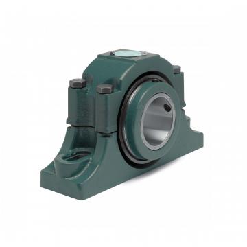 Mounted Tapered Roller Bearings P4B-EXL-212RE
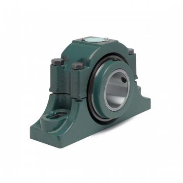 Mounted Tapered Roller Bearings P4B-EXL-400R
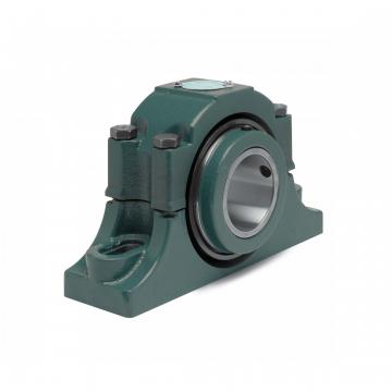 Mounted Tapered Roller Bearings P4B-EXL-400RE
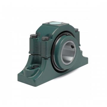 Mounted Tapered Roller Bearings P4B-EXL-315RE
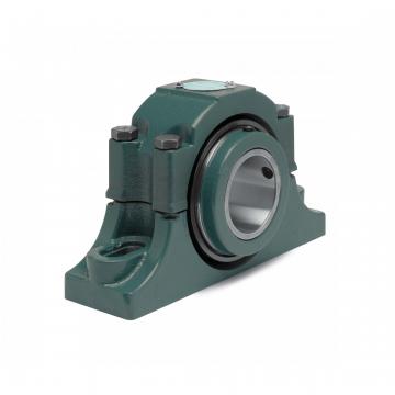 Mounted Tapered Roller Bearings P4B-EXL-207RE